

Construction
| METRICATION: 99% complete | |||
 |
|||
| Metric | Non-metric | ||
| All construction materials available in metric. | Plywood, blockboard and hardboard sold in soft metric sizes. | ||
| All design work and planning in metric. | Metric-only tape measures still uncommon. | ||
| Building regulations in metric. | |||
Metrication programme
Following the Government announcement, in 1965, that the country should switch to the metric system, the British Standards Institution (BSI) was asked to organise and co-ordinate the change in the construction industry. The Building Divisional Council of the BSI accepted a suggestion from the Ministry of Public Building and Works that advantage should be taken of the change to improve standards and include the introduction of dimensional co-ordination. Switching to a new system of measurement was an ideal opportunity to rationalise product dimensions across the whole sector.
In 1966, the BSI published BS 4011 ‘Recommendations for the co-ordination of dimensions in building. Basic sizes for building components and assemblies’. This would become the ‘head’ standard for the dimensionally co-ordinated metric changeover.
In February 1967, after a year of preparation, and in agreement with all sections of the industry, the British Standards Institution published PD 6030 ‘Programme for the change to the metric system in the construction industry’. This was followed by the publication of PD 6031 ‘A guide for the use of the metric system’.
Throughout 1967, consultations and case studies were carried out to determine key dimensional recommendations. This culminated with the publication of BS 4330, the British standard on recommendations for the co-ordination of dimensions in building.
Of all the sectors of the economy, the construction industry proved to be the quickest to initiate and successfully complete its programme of metrication.

Ministry of Public Building and Works leaflet – 1968
Units of measurement
At an early stage, it was decided to adopt the millimetre as the unit for all dimensional declarations in building design and product descriptions. This was contrary to common practice on the continent, where the centimetre was in use.
The combinations of SI units and multiples/submultiples that were permitted for use in the construction industry were laid out in Table 6 of PD 6031, the BSI’s metric guide.
Adopting the exclusive use of the millimetre had several advantages:
- For most purposes, the millimetre had an ideal degree of precision.
- For most purposes, a decimal point was not needed.
- For most buildings, each dimension can be described using no more than 4 digits.
If the centimetre had been chosen, most dimensions would have needed to be declared to one decimal place, but where a dimension was marked in whole units, there would always have been the possibility that this might have been due to a decimal point being omitted in error.
Unlike imperial, unit symbols do not need to be shown on every dimension illustrated on a metric plan. A simple note in the corner stating “All dimensions in millimetres” is sufficient.
Being able to show practically every dimension, without fractions, using no more than 4 digits means that metric building plans are much clearer than the old imperial plans. For example, a dimension of 3496, expressed in millimetres, replaces the equivalent imperial dimension of 11′ 5 5/8″.
The arithmetic needed to add or multiply the sizes of building components is also far simpler using metric.
| e.g. | |
| imperial | millimetres |
| 11′ 5⅝” + 5′ 9¼” = 137⅝” + 69¼” = 207⅛” = 17′ 3⅛” |
3496 + 1759 = 5255 |
Metric modules
BS 4330 was based on a module size of 100 mm. Essentially, it recommended that all components of a building should be manufactured in a range of standard sizes with each dimension being either equal to a multiple of 100 mm, or of a size such that when assembled in situ it would form a unit size that was a multiple of 100 mm.
The benefits of adopting such a modular system across the entire building industry had the potential to significantly reduce costs caused by reducing the amount of material wasted as scrap when items had to be cut to size on site.
A universal modular system would also allow for a reduction in the variety of commonly used sizes, which would reduce the amount of space needed for stocks of standard products.
Adopting a standard range of sizes for components such as windows, would also reduce the need for expensive bespoke production.
The metric brick
In the late 1960s, the brick industry needed to decide on a new standard brick size to meet the needs of the construction industry as it switched to the construction of buildings designed in round metric units using dimensional co-ordination based on a module size of 100 mm.
When deciding on the size for a standard brick, the most important factor is its width. A brick must not be so wide that it cannot be held in one hand. The choice of length for a brick is dependent on the width. For optimal use in a variety of bonding systems, ignoring mortar thickness, the length should be a whole multiple of the width. A length equal to twice the width allows a single brick size to be used for both stretchers and headers.
For a given width and length, the weight of a brick is directly proportional to its height, or thickness. The optimal choice of thickness for a brick is a balance between a number of factors. Thicker bricks mean less bricks need to be laid for a given height of wall, but if a brick is too thick for it to be handled in one hand, it increases the time it takes to lay the bricks.
All three dimensions must also meet the requirements for the desired module size.
In theory, the choice for the new metric brick should have been straight forward. BS 4011, the ‘head’ standard for the dimensionally co-ordinated metric changeover, clearly inferred the need to adopt a size (or sizes) based on a unit size of 100 mm. Given a nominal mortar thickness of 10 mm, a brick width of 90 mm should have been the obvious decision.
However, a formal decision to adopt a modular size for metric bricks proved to be controversial. As late as 1969, the National Builders Association (NBA) was still “not prepared to state what the size of the brick should be”, and the Ministry of Public Building and Works (MPBW) was quoted as “looking to the BSI to make the decision”. Meanwhile, the Brick Development Association (BDA) remained in favour of a compromise design that they had put forward in 1967, that closely resembled the size of standard contemporary imperial bricks. Whilst not adherent to the requirements of a 100 mm module size, the design was compatible with a module size of 900 mm × 300 mm. In January 1970, the BDA proposal was adopted by the British Standards Institution in BS 3921, and became the standard metric brick, which has now been used in new buildings for more than 50 years.

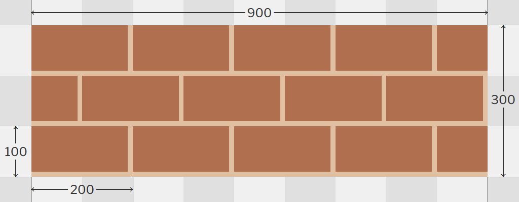
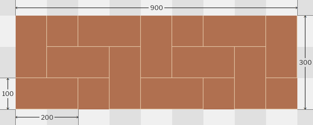
Metric bricks – Stretcher bond
The new metric brick size was 215 mm × 102.5 mm × 65 mm. Allowing for a 10 mm mortar joint, this gave a unit size of 225 mm × 112.5 mm × 75 mm.
A span of 4 bricks fills a space 900 mm wide, and 4 courses of bricks fills a space 300 mm high. 300 millimetres being the preferred module multiple in the new standard system of dimensional co-ordination as described in BS 4011.
At the time of the decision, it was also seen as an additional benefit that, with an extra 5 mm of mortar per 300 mm of bricks, the new brick could be used in existing walls built with contemporary imperial bricks.
Metric modular bricks
Even after the publication of BS 3921, the new British Standard on bricks, research into metric modular bricks continued for another year or two. There were two proposals for metric modular bricks, both based on a 100-mm module:
One had a co-ordination size of 200 mm × 100 mm × 100 mm,
giving a brick size of 190 mm × 90 mm × 90 mm.
200 mm metric modular bricks – Stretcher bond
The other had a co-ordination size of 300 mm × 100 mm × 100 mm,
giving a brick size of 290 mm × 90 mm × 90 mm.
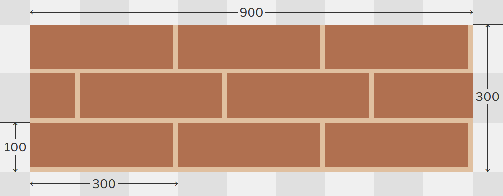
300 mm metric modular bricks – One-third bond
In 1970, the first large-scale housing scheme built in metric to the recommendations for dimensional co-ordination laid down in the Ministry of Housing’s Design Bulletin 16 (DB16) was at Warley. In 1971, The NBA also built a demonstration scheme for low-rise flats at Harlow.
Both of these trial schemes used 300 mm modular bricks. To avoid the difficulty of cutting the large 300 mm bricks, 200 mm modular bricks were used at corners, doors and windows. 100 mm bats, cut from 200 mm bricks were also used. At the trials, it was noted that the 300 mm bricks were difficult to cut into 200 mm and 100 mm pieces on account of the positioning of the brick’s four holes.
Despite positive results experienced in the trials, the use of the new BS 3921 metric brick was already sufficiently entrenched to leave little room for a ‘second’ metric standard, or for what might have been seen as back-tracking. Metric modular bricks have yet to be adopted for mainstream use in wall building.
Metric blocks
Building blocks are generally larger than bricks, and are made of concrete. They are manufactured in a variety of configurations including; solid, hollow (formed with one of more voids that fully penetrate the block), or cellular (formed with one or more voids that do not fully penetrate the block). A range of categories are manufactured for various building applications:
| Block type | Use and properties |
| Standard common block | For general building, loadbearing, good base for plastering. |
| Close textured/Paint grade | close texture suitable for direct painting. |
| Standard facing blocks | Consistent shape and texture. |
| Architectural masonry facing blocks | Available in a range of colours, textures, finishes and shapes. For applications where visual appearance is the prime concern. |
The most common application of concrete building blocks is the use of light weight blocks in the construction of the inner wall component of standard cavity walls. An important consideration when choosing the size of blocks to use for an interior wall is the module size of the bricks, or blocks, used for the exterior wall.
In January 1970, when the new metric standard BS 3921 for bricks was issued, the standard co-ordination size for blocks was for a length of 300 mm, a height of 225 mm, and for widths of 62.5 mm, 75 mm, 100.5 mm and 150 mm. Hollow blocks for floors were to have a length and width of 300 mm, and a depth varying from 75 mm to 250 mm in 25 mm increments.
In March 1971, the Concrete Block Association (CBA) recommended to its members that the following two face sizes should become the standard sizes for concrete blocks:
| Length | Height | Module dimensions | |
| Metric block | 440 | 215 | 450 × 225 |
| Metric modular block | 390 | 190 | 400 × 200 |
Both blocks were designed to be used with a mortar joint of 10 mm, and included a number of different width options.
The 440 mm × 215 mm block size is designed to be compatible with the use of standard 215 mm × 65 mm bricks:
- The length of one block plus mortar joint (450 mm) is equal to the length of 2 standard metric bricks plus joints (2 × 225 mm).
- The height of one block plus mortar joint (225 mm) is equal to the height of 3 courses of standard metric bricks (3 × 75 mm).
- The height of one block (215 mm) is equal to the height of one standard metric brick standing on its side.
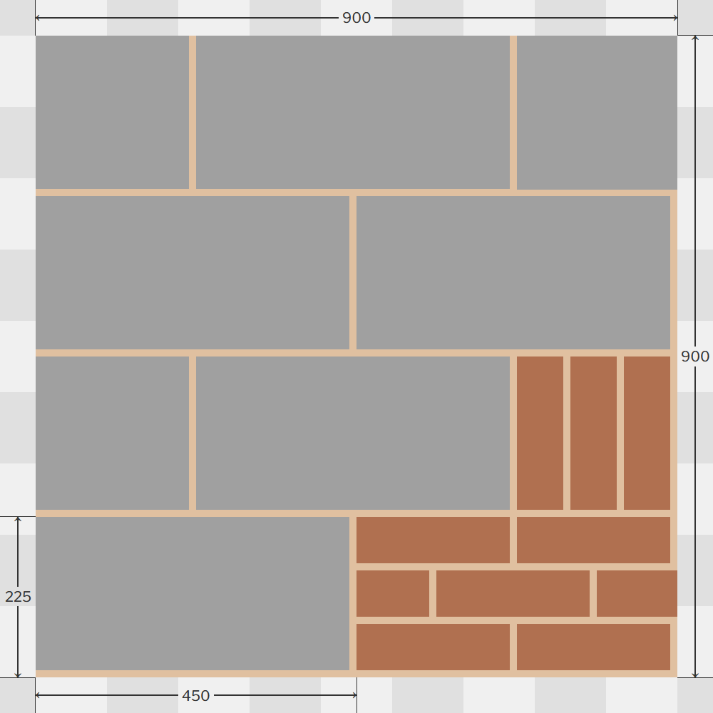
Metric blocks (with metric bricks) – Stretcher bond
The 390 mm × 190 mm block size is a fully modular design, compatible with the use of metric modular bricks, or with other components using the 100 millimetre module dimensional co-ordination system.
- The length of three blocks plus mortar joints (3 × 400 mm) is equal to the length of 4 metric modular bricks plus joints (4 × 300 mm).
- The length of one block plus mortar joint (400 mm) is equal to the length of 2 short metric modular bricks plus joints (2 × 200 mm).
- The height of one block plus mortar joint (200 mm) is equal to the height of 2 courses of metric modular bricks (2 × 100 mm).
- The height of one block (190 mm) is equal to the height of one short metric modular brick standing on its side.
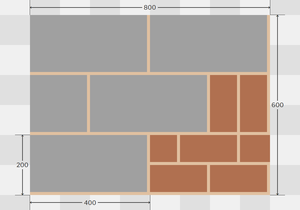
Metric modular blocks (with metric modular bricks) – Stretcher bond
Standard metric concrete blocks – available widths
| Width | Face size | |
| 450 × 225 | 400 × 200 | |
| 75 | ⬤ | |
| 90 | ⬤ | ⬤ |
| 100 | ⬤ | ⬤ |
| 140 | ⬤ | ⬤ |
| 190 | ⬤ | ⬤ |
| 215 | ⬤ | |
Paving slabs
From 1 April 1970, paving slabs in the following standard metric sizes became available:
| Type A | 600 × 450 |
| Type B | 600 × 600 |
| Type C | 600 × 750 |
| Type D | 600 × 900 |
Block paving
The standard brick size used in most modern block paving has a module size of 200 mm × 100 mm.
200 mm metric modular block paving – Herringbone bond
Windows
In 1965 and 1966, the metal window industry launched its Module 4 range of window sizes. Based on a module size of 4 inches (101.6 mm), window sizes were based on increments of two modules in height and three modules in width. The timing of the move to a modular window system based on imperial units was unfortunate, being just two years before the publication of the British Standards Institution’s metric module standards.
However, the experience gained in the design of the Module 4 range was invaluable when the need came to switch to the 100 mm module. Rather than immediately revising all dimension from multiples of 4 inches to multiples of 100 mm, the Module 4 designers joined industry-wide discussions with the BSI’s Functional Group Panel to reach agreement on preferred sizes.
In 1967, committees of the Metal Window Federation and the Steel Window Association undertook a two-year study on dimensional co-ordination for window production. This research culminated in 1969, with the publication of a list of recommended metric modular window sizes. The sizes, or more strictly-speaking the ‘spaces’, were based on the matrices produced by the BSI Functional Group Panel’s External Envelope, which in turn had been derived from BS 4330.
Steel windows in the metric Module 100 range became available in 1970, and from January 1971 were standard. From January 1971, the old imperial Module 4 range were available only on special order. From 1973, all steel windows in imperial sizes were subject to a surcharge.
A guide on aluminium window sizes resulted from the work of the Metric and Dimensional Co-ordination Committee of the Metal Window Federation and the Technical Committee of the Aluminium Window Association. As was the case with steel windows, standard metric modular spaces for aluminium windows were derived from the BSI’s External Envelope matrices.
From January 1970, aluminium windows switched to metric sizes for the standard range. Imperial sizes continued to be produced, but by special order only.
The British Wood Manufacturers Association (BWMA) submitted their proposals for metric sized timber framed windows in 1970.
Doors
Prior to metrication, the standard height of a door space was 20 modules, or 2032 mm, where one module was equal to 4 inches (104.6 mm).
Adopting a door space with a height of 20 metric modules, or 2000 mm, using the new 100 mm module size, would have lead to the clearance height of metric door frames being a hazard for a greater percentage of the population than imperial door frames. Consequently, the new metric door space was set at 2100 mm. This also had the advantage of being a whole multiple of 300 mm, the preferred module increment in BS 4330.
Plasterboard and plaster
In 1970, The British Standards Institution (BSI) revised two standards for panel materials, and updated them for the metric system:
BS 1230 ‘Gypsum plasterboard’: Part 2: 1970 ‘Metric units’ specified the metric sizes and quality requirements for gypsum wallboard, plank lath, baseboard, and insulating plasterboard.
BS 4022 ‘Prefabricated gypsum wallboard panels’ gave specifications in SI units, and superceded the 1966 edition of the standard.
From April 1970, in keeping with the BS 4330 preferred module multiple of 300 mm, all new wallboard manufactured by Bellrock Gypsum Industries’ became available only in the new metric widths of 900 mm and 1200 mm. The new metric lengths were 1800 mm, 2400 mm, 2700 mm and 3000 mm. Board thicknesses remained unchanged from imperial, but were now quoted as 9.5 mm and 12.7 mm. Existing imperial wallboard stocks remained for sale by special order, but were finally withdrawn from sale before April 1971.
Plasterboard and partitions were also invoiced in square metres from April 1970.
From 1 February 1971, wholesale plaster switched to weights in tonnes, and decimal currency for all invoicing.
Timber
From 1 April 1970, the sale of timber switched to metric sizes. Starting with 1800 mm, lengths were available in increments of 300 mm.
 |
||
| Timber metrication leaflet – 1970 | ||
The new metric range of widths and thicknesses were direct conversions of the old imperial sizes. To calculate every new metric size, each inch was substituted by 25 mm, with the result being rounded to the nearest millimetre.
Standard metric sizes for sawn softwood – 1970
| 75 | 100 | 125 | 150 | 175 | 200 | 225 | 250 | 300 | |
| 16 | ⬤ | ⬤ | ⬤ | ⬤ | |||||
| 19 | ⬤ | ⬤ | ⬤ | ⬤ | |||||
| 22 | ⬤ | ⬤ | ⬤ | ⬤ | |||||
| 25 | ⬤ | ⬤ | ⬤ | ⬤ | ⬤ | ⬤ | ⬤ | ⬤ | ⬤ |
| 32 | ⬤ | ⬤ | ⬤ | ⬤ | ⬤ | ⬤ | ⬤ | ⬤ | ⬤ |
| 38 | ⬤ | ⬤ | ⬤ | ⬤ | ⬤ | ⬤ | ⬤ | ||
| 44 | ⬤ | ⬤ | ⬤ | ⬤ | ⬤ | ⬤ | ⬤ | ⬤ | ⬤ |
| 50 | ⬤ | ⬤ | ⬤ | ⬤ | ⬤ | ⬤ | ⬤ | ⬤ | ⬤ |
| 63 | ⬤ | ⬤ | ⬤ | ⬤ | ⬤ | ⬤ | |||
| 75 | ⬤ | ⬤ | ⬤ | ⬤ | ⬤ | ⬤ | ⬤ | ⬤ | |
| 100 | ⬤ | ⬤ | ⬤ | ⬤ | ⬤ | ||||
| 150 | ⬤ | ⬤ | ⬤ | ||||||
| 200 | ⬤ | ||||||||
| 250 | ⬤ | ||||||||
| 300 | ⬤ |
The switch to metric units for hardwood was more gradual:
- From 1 April 1970, hardwood suppliers agreed to supply invoicing in metric upon request, but sales remained in imperial units.
- From 1 January 1971, stock-keeping and sales switched to metric units.
The new metric range of thicknesses for hardwood were a subset of those adopted for softwood. In millimetres, the available thicknesses were:
19, 25, 32, 38, 50, 63, 75, 100, 125
 |
 |
|||
| Wood and Board – metrication leaflets | ||||
Plywood and blockboard
When plywood and blockboard switched to being sold in metric units, the 100 mm module was ignored.
Surface dimensions, which had previously been in multiples of 6 inches, were converted to millimetres using the exact conversion formula of 25.4 mm to one inch, and then rounding to the nearest 5 mm.
Surface dimensions
| inches | millimetres |
| 36 | 915 |
| 48 | 1220 |
| 60 | 1525 |
| 72 | 1830 |
| 84 | 2135 |
| 96 | 2440 |
| 108 | 2745 |
| 120 | 3050 |
| 144 | 3660 |
Thicknesses also switched to nominal metric thicknesses in millimetres. Thicknesses, which had previously been in multiples of 1⁄16 inch, were converted exactly, and then rounded to the nearest 0.5 mm.
Plywood and blockboard thicknesses
| inches | millimetres |
| ⅛ | 3.2 |
| 3⁄16 | 5.0 |
| ¼ | 6.5 |
| 5⁄16 | 8.0 |
| ⅜ | 9.5 |
| ½ | 12.5 |
| ⅝ | 16.0 |
| ¾ | 19.0 |
| ⅞ | 22.0 |
| 1 | 25.5 |
| 1¼ | 32.0 |
| 1⅜ | 35.0 |
| 1½ | 38.0 |
| 1⅝ | 41.5 |
| 1¾ | 44.5 |
| 1⅞ | 47.5 |
In effect, when switching to metric size declarations, plywood and blockboard product sizes did not change from when they were imperial. All product dimensions remained within the tolerances of the new nominal metric sizes.
The consequence of not adopting metric modular sizes for plywood, is not just that we no longer have a range of products with round dimensions, it is that cutting is always required, and waste is inevitably generated every time plywood is used in a metric modular building. If a length of 2400 mm is needed, then 40 mm of board has to be cut from a 2440 mm board as waste.
Glass
On 28 September 1970, Pilkingtons switched to metric measurements and decimal currency, for all flat glass and fibreglass products.
Standard sizes of Armourplate glass doors and Glastoglas double glazing units continued to be supplied for some time, to fit existing units, but new metric sizes were offered for new metric frames.
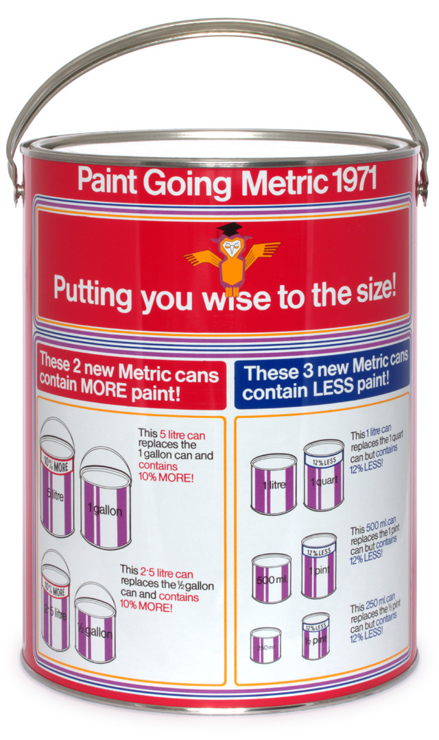
Paint
Paint in metric cans was first available from merchants and retailers in June 1971. Five metric sizes replaced the previous sizes of pints, quarts and gallons:
 |
 |
| Old imperial size | Size change | New metric size | Date introduced |
| 1 gallon | 10% more | 5 L | June 1971 |
| ½ gallon | 10% more | 2.5 L | mid July 1971 |
| 1 quart | 12% less | 1 L | end August 1971 |
| 1 pint | 12% less | 500 ml | October 1971 |
| ½ pint | 12% less | 250 ml | October 1971 |
The first available metric size was the 5 L tin – which replaced the old 1 gallon size. The whole metric range was available by December 1971. However, existing stocks of imperial cans remained available for some time afterwards, especially the slower moving colours. To avoid confusion during the transition, new cans were labelled in dual units – metric first with imperial equivalent in brackets.
The new metric tins’ spreading capacities were given in square metres.
Roofing felt and damp-proof courses
Originally planned for 1971, the manufacture of roofing felt and damp-proof courses switched to metric measurements in January 1972.
Building Regulations
On 1 June 1972, The Building Regulations 1972 came into force. These new all metric regulations consolidated all the changes that had been made since The Building Regulations 1965, including the switch to metric standards throughout the building industry.
Government policy
Towards the end of 1970, just two years before completing the bulk of their metrication programme, there was consternation in the construction industry at the Government’s growing lack of enthusiasm for metrication.
Little visible progress was being made in the wider economy, and recent Government statements were adding to fears that metrication might be forced into reverse. A half-hearted change, followed by a reversal, would have been the worst of all possible worlds.
The Government’s announcement, on 9 December 1970, that it was dropping plans to switch to metric speed limits in 1973, had a chilling effect for everyone currently undergoing the short-term expense of the metric transition. Government assurances that it would ‘not impede’ further metrication in the construction industry were not very encouraging.
The construction industry of course was not working in isolation from the rest of the community. Many of its goods came from industries supplying the domestic market. It made no sense to be a country in which its major industries measured in metric, and which was about to switch to a decimal currency, but in which domestic life continued to be carried out in imperial.
Action required by : DIY retailers
- Measuring tapes – Metric-only measuring tapes and steel rulers need to be made widely available.
FUN FACT :
300 mm can be divided equally in 18 different ways:
1, 2, 3, 4, 5, 6, 10, 12, 15, 20, 25, 30, 50, 60, 75, 100, 150, 300.
1 foot, or 12 inches, can be divided equally in only 6 different ways:
1, 2, 3, 4, 6, 12.
